


Rural Internet Enhancement Solution
By offering long-range and low-power of Wi-Fi HaLow™ enhances wireless connectivity in rural areas, providing improved reliability and coverage. Additionally, its resilience to weather and

Agricultural IoT Device Solution
Revolutionizing agriculture with Wi-Fi HaLow™ IoT Device Solution, enabling efficient and sustainable farming practices through advanced connectivity and data-driven insights.

Energy Sensor Remote Control Solution
Harness the power of Wi-Fi HaLow™ technology for efficient energy management through real-time monitoring, remote control, reliability, and scalability.

Robotics: Revolutionizing Automation
In recent years, robotics has emerged as a game-changing technology, with the advent of advanced connectivity solutions like Wi-Fi HaLow™, robotics is entering a new

Wi-Fi HaLow in Healthcare
With its low-power, long-range wireless communication capabilities, Wi-Fi HaLow™ is revolutionizing connectivity in healthcare, leading to advancements in patient care, remote monitoring, and operational efficiency.

Factory Automation
Factory automation has driving efficiency, productivity, and cost-effectiveness. To further enhance automation capabilities, advanced connectivity solutions like Wi-Fi HaLow™ are playing a pivotal role in

CEO Column / Industry Insights / April 2026

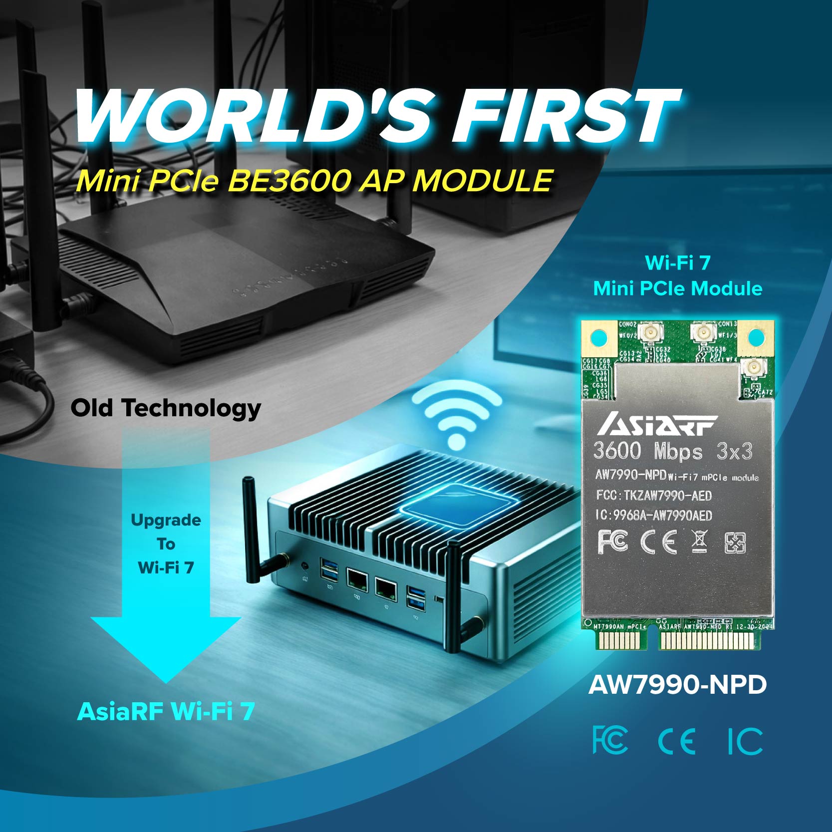
Overcoming Hardware Constraints: The Strategic Impact of AW7990-NPD as the World’s First Wi-Fi 7 Mini PCIe Module

AsiaRF Recognized as One of the FT High-Growth Companies Asia-Pacific 2026

WiBRAVO : Absolute Velocity. Pure Intelligence.

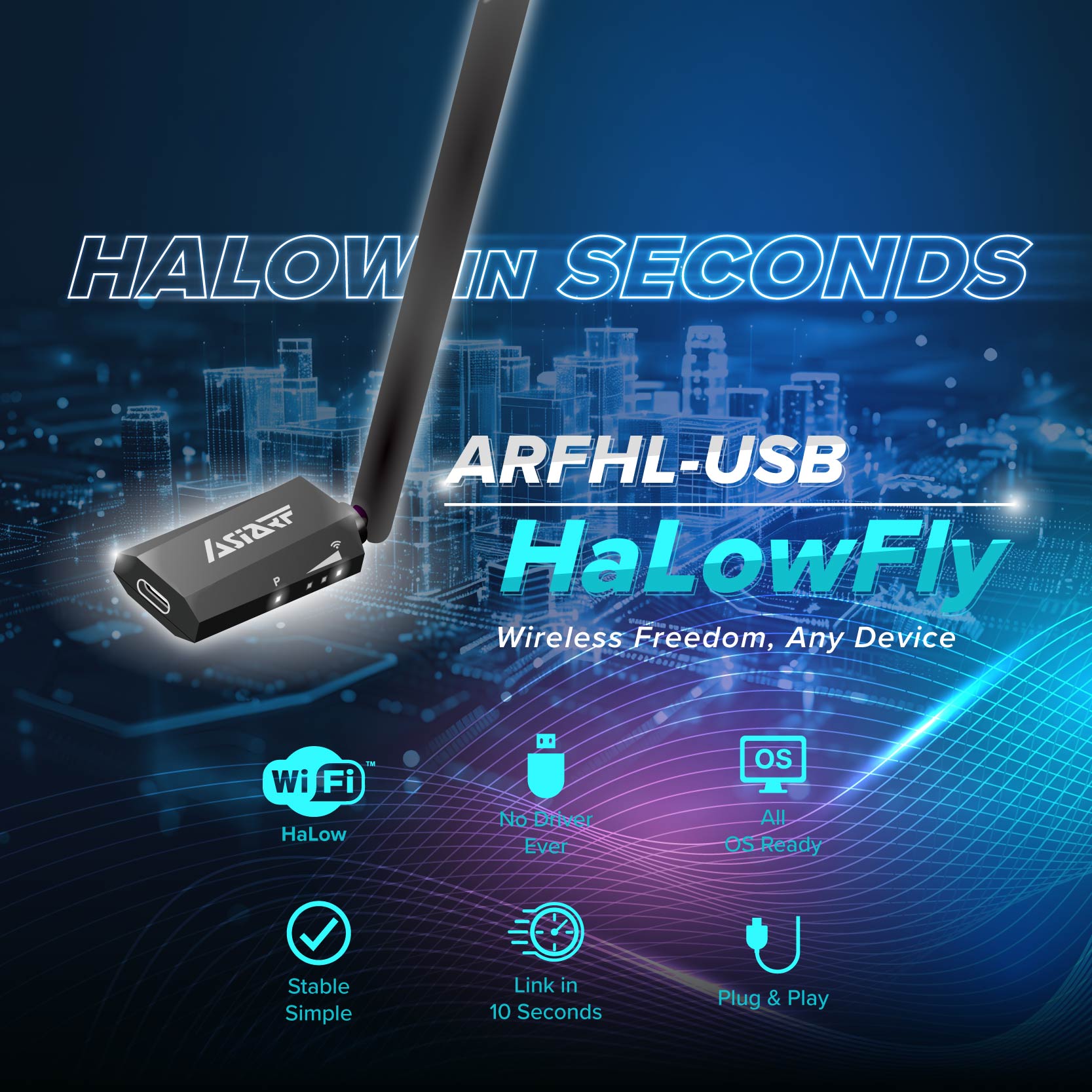
Eliminating Dead Zones: Real-Time Signal Monitoring with HaLowFly
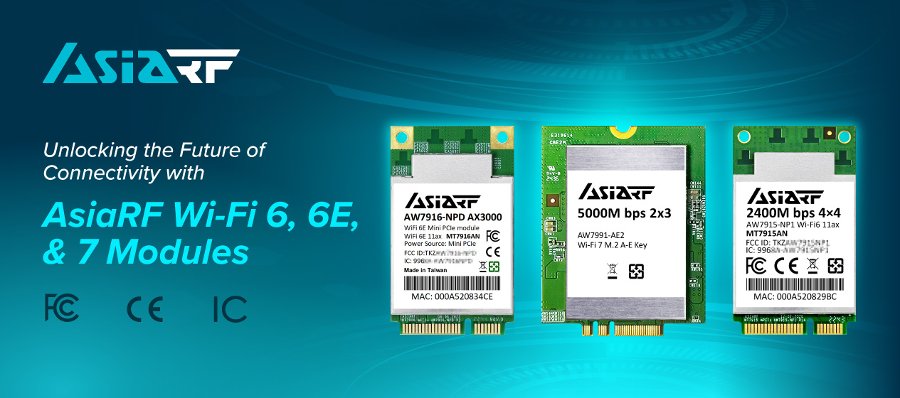
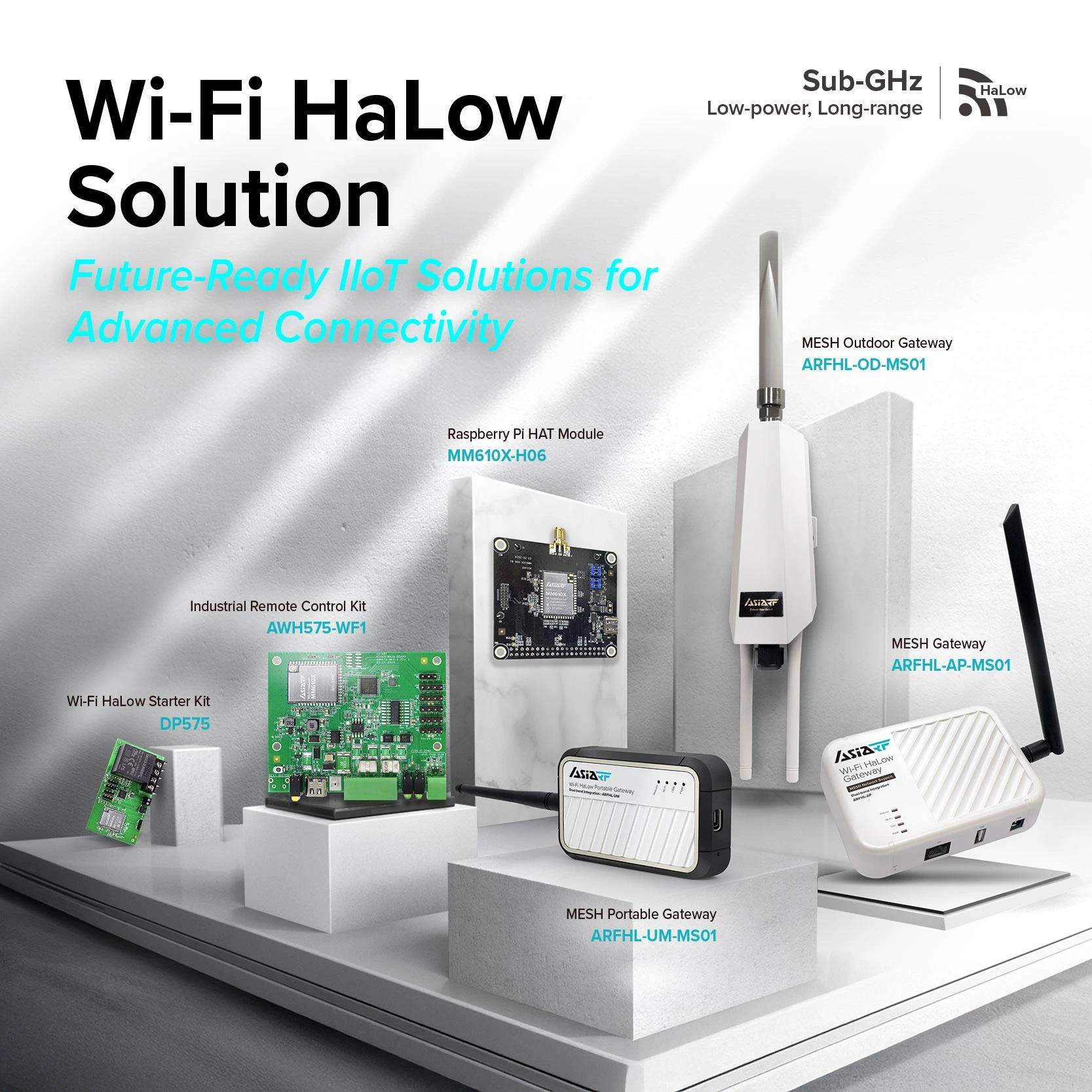
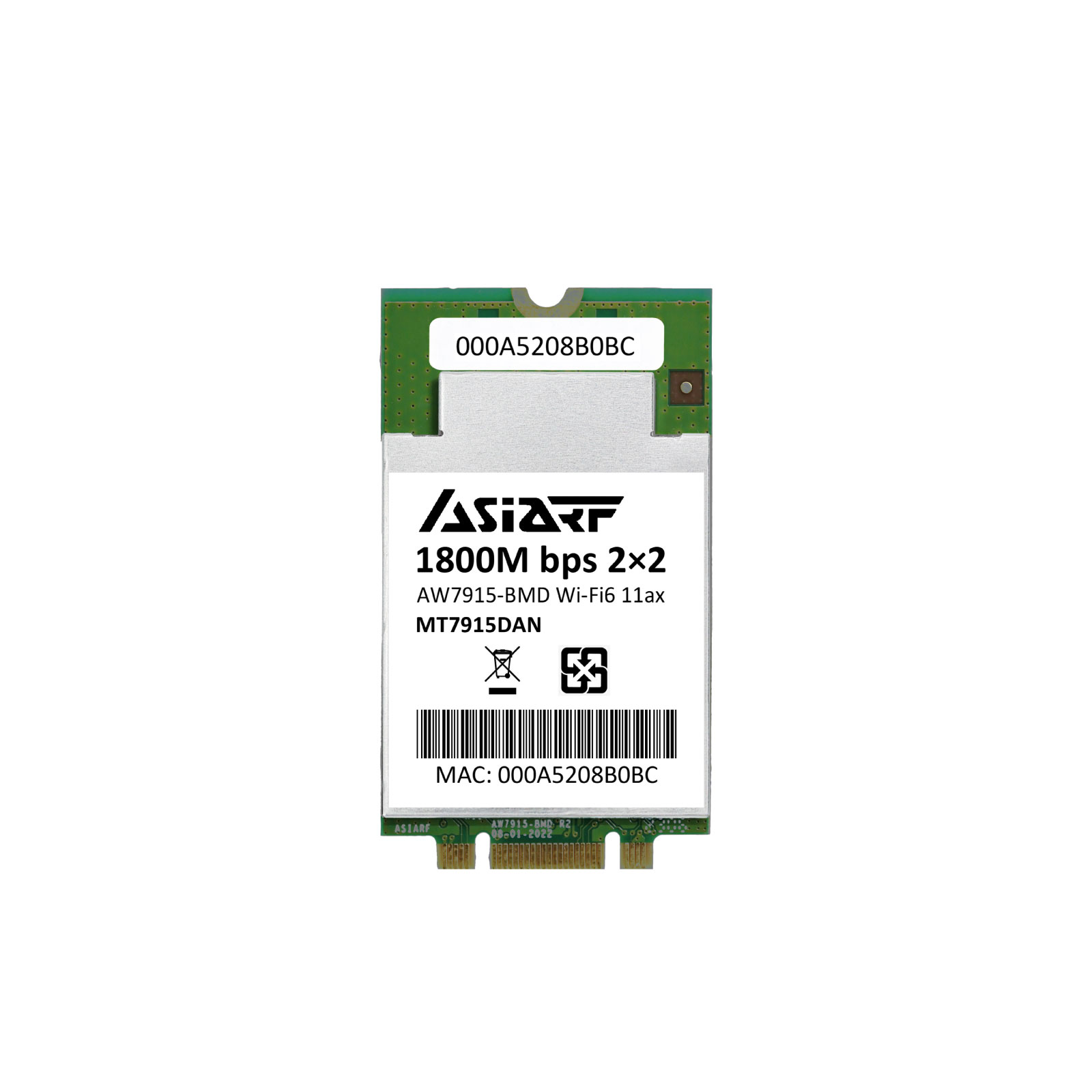
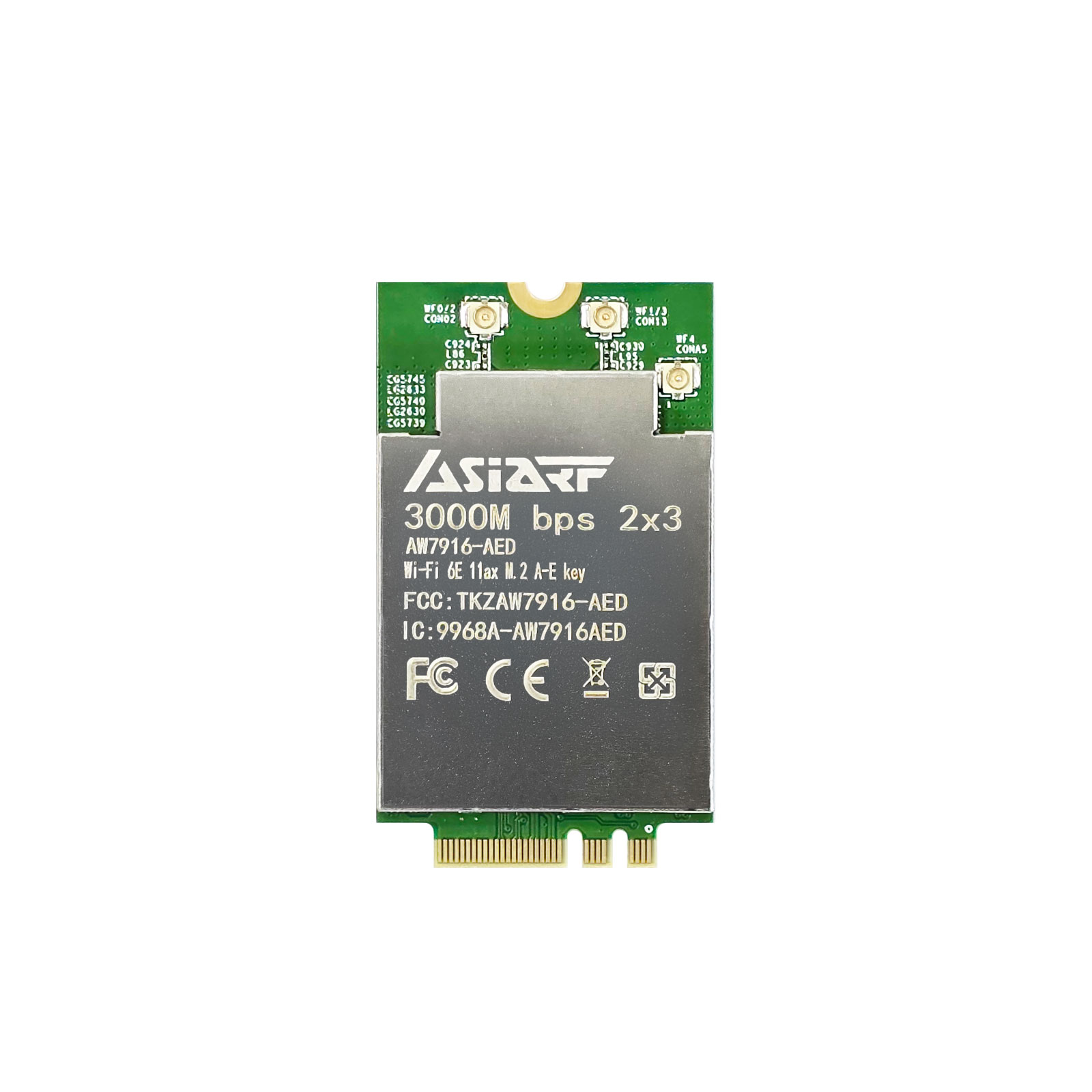
How to Use AsiaRF Wi-Fi 5, 6, 6E, and Wi-Fi 7 Modules